Followers

Thursday, July 9, 2015

"STARTING" Track Plan and 3D model

OK, BUT FIRST MUST ADMIT TO DOING MO[O]RE "TRAINING":


With the research car measuring the "pull" like we did in the late 70's with 2-10-4, T&P 610


with some encouragement of the man at the throttle:


OK, enough of the real, let's get onto the model railroad.

Below is the schematic of the track plan as the builders of the V&T Rwy now see it:


The names are real and the starting point for the layout [could be changed like so much else] between Hagerstown, MD to east Tennessee but bear no resemblance in location to each other other than Hagerstown, MD, and Rockwood, TN.  The numbers in RED are locations marked with little yellow sticky notes on the track plans [below].  The track plans were laid out on graph paper with two blocks [1/2 inch] = 1 ft. and curves and switches drawn out in that scale.  There are three basic levels.  Starting at the top, Hagerstown staging [1], is a 1.28% grade to Saltville [6] with Ozone [2] being level from switch to switch.  The single ended tracks at Devonia [3] are on the level but the main behind them is on the grade [yes, a "holding" mechanism is needed on the main here].


Brimstone [4] and LaFollette [5] are on the grade since they are only holding tracks for complete trains, essentially staging tracks,  and no switching done there.  Saltville [6] is level.  Saltville to Elza Gate [10], the bottom of the helix, is on a 2.8% grade and will require helpers for some trains.  


ELEVATIONS

These grades put the second level, Saltville [6], at 58 inches [making the "nod under at the door at about 56 inches] and 5 inches under the top level, Hagerstown [1] at the door and the wall on the right entering the room [wall 4] [at 63 inches] .  

The main level, below, is at 46 inches which includes ALL track shown below.


LENGTH OF RUNS

Gate City yard [11] to Dixianna [14] is 20 ft [0%rise]
Elza Gate [10] to Piney River [8] is 27 ft. [0%rise]
Gate City yard [11] to Saltville [6] is 37 1/2 ft.  [2.8%rise] [helpers may be needed]
Saltville [6] to Hagerstown [1] is 75 ft  [1.28%rise]

Which makes the mainline run from Gate City yard [11] to Hagerstown [1] 112 ft

ADDITIONAL 1 inch =1 FT plans to be done of the various towns/industries/switching areas which are are still being developed/finalized.  For instance, the below three plans show possible options for Dixianna [14]/Morley [13] and Saltville [6] [these are at the 1/2 inch - 1 ft]:


SORTA PROVING THE TWO DIMENSIONAL PLANS:

To confirm that these two dimensional plans were "do-able" when built, one level over the other, a 3D 1" [four squares] = 1 ft model was built.  Graph paper was glued to the foam-board "wall" so all three dimensions scaled out.  Matboard was cut to for the layout surface and held in place with straight pins through the foam-board "walls".


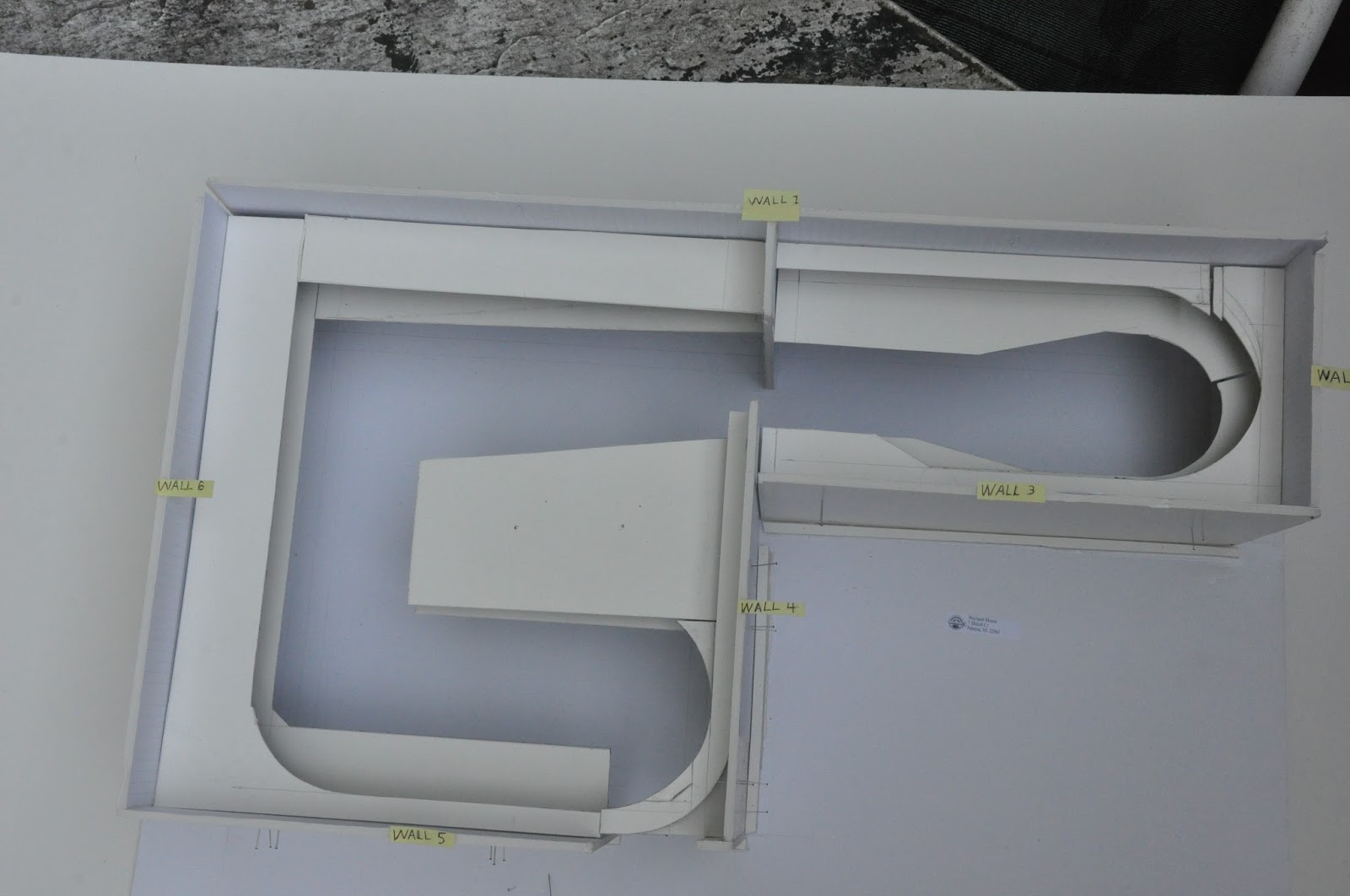
Here is a close up of a couple of the wall surfaces showing two and three levels:


OK, finally got this to where it should be posted, 3:03 am, and will start on cleaning up some things this morning.  Bye, bye or "Good Day, mate"

Friday, June 26, 2015

UPDATE!!

I have "feasted" on many other layouts in the past few months.  Now is the time to reduce the level of being a "boomer" and  get on with the V&T Rwy.  However, the "real thing", both steam and diesel and the NS Steam Program which is MUCH more active this year, will get some of the time.


 The "starting point" layout design showing basic benchwork and elevations, yards, industries and towns has been completed.   Details of some town and industry areas are roughed in but not all are yet "finalized".  A number of options have been sketched out for all towns and industries.  However, this is the starting design and more than enough to start.  Also completed is a 3D model, 1" = 1', of the layout.  This model provides a needed perspective since some walls of the layout will have up to three levels of track.  Track plan and photos of the 3D model will be posted shortly.

On the way to the Southern Railway Historical Association convention I stopped in Saltville, VA, and learned more about the chemical companies that had been there.  Olin chemical operation had raw materials of salt from the ground and limestone coming in on cable buckets and output was soda ash, caustic soda, carbonates, chlorine and dry ice [the largest such plant in the world].  The other Saltville company produced plaster.  In the nearby area was the Holston River Lumber Company which had Shays feeding the mill.  Later trucks brought logs to a smaller mill but output still included rail.  Even though much of the manufacturing ended in the 70's, there was a lot going on in my modeled timeframe of the mid 50's.  Output from these industries will feed other businesses on and off the layout.  This background information forms a basis for the type, and to a lesser degree, number of the cars to serve these industries.

And there has been some progress in opening up space in the train room.  Cleaning caulk and ballast from the used Peco track is more than half complete and the switches, of which there are almost 50, is complete.  Once completed the closet will be open to start "cutting wood".  In the train room itself, other track and switches are being put in one easy to find place.  The same goes for tools, out of the UPS and USPS boxes and into the storage containers, with labels, that had been bought for them.

Sunday, February 1, 2015

Email notification check

Please email me if you get an email from my V&T Rwy blog.  Some folks said that they signed up for email notifications but were not getting them.  This is a check to see if that is working.  It also provides a bit of history on train control.  I will email the attachment mentioned below:


 "The Bell Code" - A Curious Way to Run a Railroad
A certain friend in NY City recently asked me for information on "the Bell Code."  So I put together the attached PDF, scanned from the 1896 edition of "The Standard Code of the American Railway Association - Train Rules, Block Signal Rules."
The Bell Code was part of the Standard Code of Train Rules and Block Signal Rules for a while, and was then dropped.  I do not have enough editions of the Standard Code to know when the Bell Code was introduced and when it was dropped, but I do know it was gone by 1920.
The Bell Code used in America was a replication of the system that has served in Britain for more than a century and a quarter.  Towers ("Signal Boxes," in British parlance) communicate with each other about the moving of trains by sending prescribed number of taps on bells, each combination of taps having assigned meanings -- no Telegraph or telephone is involved.
But why was such a clumsy system ever employed in the United States, where everyone employed in tower service, Train Order service, and the movement of trains, already knew Telegraphy and had the Telegraph at their disposal?  Infinitely more information could be sent quickly by Telegraph, than by jangling bells.  What railroad(s) used it, and why, is a mystery to me. 
At first I thought that the Bell Code may be someone's attempt to run a railroad without paying for skilled workers called Telegraphers, who could communicate messages by Telegraph.  But if the railroad were operated by non-Telegraph people, how would Train Orders be handled (and remember, this was a day before telephones were sufficiently developed to be used in Train Dispatching service.)  Even if the railroad were operated without Train orders, how would the directives of the Train Dispatcher be communicated, if the operators were non-Telegraphers?  So it is a mystery.
Another thing about the Bell Code is worthy of mention.  Namely, that it is embedded in a section of rules which describe the "Controlled Manual Block" method of moving trains.   Controlled Manual Block is worthy of a study in its own right, to determined which roads used it and its various permutations.  I have found only two places it was used on the Pennsylvania Railroad:  (1) On the "Third Track" between Spruce Creek and Tyrone Forge, Pa, on the Middle Division, beginning in the late 1880s and (2) on the Jamesburg Branch in New Jersey (but I have no dates or details on that operation.)  As implemented on the PRR, the operators at each end of the block had to cooperate by having their levers in corresponding position before a signal could be obtained for a train to enter the block at either end, and the safeguard was enforced by electric locking of the signal levers, but those men also had Telegraph (and later, telephone) at their disposal.
If anyone has a list of where the Bell Code and Controlled Manual Block were used, I'd be interested in seeing it.
-- adb

Friday, December 19, 2014

So you thought this train would never come in.  Well, ran into a lot of wet leaves on the uphill grade and the coal in the tender was like Alabama swell belly.  Management sells the good coal and we get this "dirt".  Anyway, this post is not to tell you of the completion of the perfect track plan that will never have to be adjusted.  It is to tell you what has been done.

Continued the cleaning out of the storage room - some of the VHS tapes went into the trash.  Almost all of the film camera equipment and materials have been sold which freed up more of the storage room.  Doug Barry helped in disassembly of the "L" guider from the old layout and this wood will be used on the new layout.  Some HO engines and cars that are not time appropriate for my friends or myself have been passed onto eBay selling.  The shelving in the downstairs bath was completed and some G scale locos were put on display.


Comments on the lower level plan in the closet, which includes the yard, were provided by Keith Stillman and Dick Munnikhuysen - make sure there is aisle space.  


This plan is bad on two counts:

1.  A lot of aisle space is eaten up trying to put the turntable directly across from the yard.
2.  Reach to hand throw switches on the yard ladder is bad - reaching over tracks.


This plan is better but the turntable still has not been located.  Bob Warren, Paul Dolkos and Doug Barry have all counseled "get cutting wood/buikding".  An excess 12" diameter turntable from a visit at Tony Koester's is providing the impetus to locate it on the layout at the end of the closet.  In the future I'll try to get plan photos that are easier to read.


Talked to Dan after Paul Dolkos's comment about "don't see the theme" and came up with "MINERALS".  So, in addition to the American Cyanamid plant at Piney River, VA, the Olin Mathieson plant at Saltville, VA, will serve as prototype inspiration for two major customers in the layout room. And it has since been discovered that the type of chemicals Olin Mathieson sold could have been used at the American Cyanamid plant. 

One of the "wet leaves" delays was reading about a now defunct short line in Kentucky.  One of the authors worked for the line and the book included an interesting description of switching a distillery.  Talking and emails with the book's co-author gave me incentive to look into including this.  With the location of the modeled portion of the V&T Rwy being in southwest Virginia and northeast Tennesse and Jack Daniel being located in Lynchburg, TN, in the dry county of Moore, the V&T may just have another major customer.

And there is still the connecting lines/branches/interchanges of coal and wood as well as a few local small businesses.


I started looking at space consideration in the closet.  Brackets for the lower level were put in place and shelving laid across the get a feel for aisle vs depth of layout.  This mess is a result of beginning to pull out and get an idea of track and switches on-hand.  Several sheet of plywood and Homasote have been purchased.  The screw-in connectors that go in the recessed lighting have been procured and initial information on track lighting obtained.  

From the last posting "FOR THE NEXT TIME" there is still much to do.

NEW:  FOR THE NEXT TIME

There is a 100 inch long piece of serpentine track from the old layout now in the basement for the checking of trains on different grades with specific locos.  
ADDED: Set up Digitrax power supply to power test trains. Still need to do this.  It would REALLY help me to know if there is any advantage to use AC versus DC to power the Digitrax - your thoughts are solicited.

Drawing up scale drawings of track arrangement.  Still need to do this.

Establishing a line diagram for the modeled right-of-way and an "operating scenario".  Still need to do this.

Identifying the lighting for the train room and closet [probably fluorescent  or LED track lighting].  ADDED: Review electric current ratings supplied to the rooms.  Lighting identified but much work remains.


Clean out the train room that is currently totally full [this is from both Doug Barry and Steve Robbins - even the wife suggested a POD but it doesn't provide the humidity control that a lot of the "stuff" needs but some of it is going into the shed].

Thanks for reading - and Best of the Holidays to all.


Friday, June 13, 2014


Well, it's been under three months [just barely] since the last post.  And there has been action, but not as much as desired in the layout area.  The motorcycle was sold and what does this have to do with the V&T Railway? inquiring minds want to know.  It frees up space in the shed which provides more space for things in the basement to get moved into the shed which in turns provides more space in the part of the country to be served by the V&T Rwy.  Then in mid May Will, the younger son, come up to be the lead contractor for installation of the vertical supports in the closet AND the bath.  Why the bath?  I hear those gears grinding - well added some shelving to display some of the "G" scale "narry" gauge.    


Here Will is measuring to locate the vertical supports and then getting a level line so the three supports will be even and level.                                                                                                                                


This next photo shows how we got the supports in the closet to match the height in the trainroom - just punched a hole in the wall about where the track will be placed.  The yard located in the closet will be the widest area supported off the wall and it could be as wide as two feet so double channel was used along that one wall and the end wall.  Since the spacing of the slots in the double channel is 1 1/4 inch and the single slot is 1 inch, a key slot level was established at the height for the yard and that level brought through the wall and around the three walls in the closet [in the closet, two walls to have double slot, the other wall and all walls in the train room have the single slot].  


This photo shows establishing the height for the single slot support based on the adjorning double slot support.


The double slot brackets have two holes in them for screwing the wood benchwork to the brackets as shown below:


Since the single slot brackets have no method for attaching the benchwork, there needed to be a "magical" answer.  Will suggested a pipe bracket but Chris Schieck suggested cutting angle into little brackets, drilling appropriate holes [intuitively obvious]  I decided that pop rivets would be a quick. solid and easy method to attach the little bracket to the single slot bracket.


Looks like its going to work.

From the last posting "FOR THE NEXT TIME" there is still much to do.

NEW:  FOR THE NEXT TIME

There is a 100 inch long piece of serpentine track from the old layout now in the basement for the checking of trains on different grades with specific locos. 
ADDED: Set up Digitrax power supply to power test trains.

Installation of the wall shelving in the closet - uprights completed.

Drawing up scale drawings of track arrangement.

Establishing a line diagram for the modeled right-of-way and an "operating scenario".

Identifying the lighting for the train room and closet [probably fluorescent  or LED track lighting].  ADDED: Review electric current ratings supplied to the rooms.

Thanks for reading.  Comments and questions appreciated.


Tuesday, March 25, 2014

Except for failure to do posting, both planning and work have progressed in the past 3+ months.  On the planning side, received comments from a couple of you on the last post of layout plan. Mike Garber copied the pencil plans from the blob, marked them up and sent his thoughts and questions as an attachment to an email.  Thanks Mike, that made it very easy to respond.  And am sorry that some of you could not see all the information easily but am focusing on planning/building layout, not a blog.  However, have not reduced the file size for the photos of the penciled track plan as much as before, again took some time to try to enhance the photos and presented them in a large format to try to make it easier to view.

Also received a number of ideas from Bob Warren.  Most folks I have talked to prefer and are more comfortable with a single level layout and Bob is one of them.  With every track plan for the layout, he included a discussion specific layout plan, thoughts on operations and a line diagram:


I first asked for input on the yard in the closet and got the following:
  

Next came working on the entire area for a two level layout.  One of the things he tried to do is to increase the length of the run for the nolex by starting it at the far end of the closet instead of at the wall between the closet and train room. 


The first two plans were "B" and "C", the upper level the same for both of them.  Shown in order below are "B" [lower level], the alternate lower level "C" and finally upper level for both "B" and "C":


Next came the another two level design:


And another two level design:


And then a 1 1/2 level design with single end staging:


While the yard design was detailed and scaled out, much of the other plans were more of just the concept nature.  He certainly put more in the design than track arrangement by providing the discussion and line diagram.  The description of operation and line diagram has provided some pretty neat ideas even if my initial build remains little changed from the plan in the last post.

I have continued to gather ideas in the form of photographs of construction methods as well as both photos and emailed electronic documents of operating documentation like card cards, waybills, schedules, etc.  Below are photos of Seth Gartner's beautiful New York Central Piney Fork Branch that show what I have in mind for the nolex:


After looking at the construction Keith Stillman used for his upper level [using double slot wall shelving]:

and seeing Chris Artale's storage shelves in his garage using single slot wall shelving on 32" centers, have decided to go with the single slot wall shelving on 16" centers in the train room and double slot in the closet [the yard in the closet is going to be considerably deeper than any place in the train room that is against the wall].  And have also adopted Chris's suggestion of having the vertical supports tall enough to have a storage shelf both above and below the layout.

About a month ago I moved lots of stuff away from the walls in the train room and younger son, Will, came up from Williamsburg and we got "water level" marks in both the train room and closet and vertical supports in place in the train room.  I got the ceiling painted, some shelving in place at both the lower and upper levels.  


Recognizing that there is a desire to put as much operation/track into the limited space and also to provide realistic information for planning, I cluttered up more of the basement with a two level mock-up.  The large box provides a 10 inch height, the cardboard is 12 inches deep over the lower level in these photos and the lip is 2 1/2 inches high.  V & T Rwy track standards were derived from the mockup which provided information as to the closest that a track can be to a vertical surface and closet track spacing [1 1/2 inch and 2 1/4 but 2 1/2 inch better, respectively].   


FOR THE NEXT TIME

There is a 100 inch long piece of serpentine track from the old layout now in the basement for the checking of trains on different grades with specific locos.

Installation of the wall shelving in the closet.

Drawing up scale drawings of track arrangement.

Establishing a line diagram for the modeled right-of-way and an "operating senario".

Identifying the lighting for the train room and closet [probably fluorescent  or LED track lighting].

Thanks for reading.  Comments and questions appreciated.