Had the flag out today and in by sunset.
It's been less than three months since the last post. Yeah! Improvement.
And there has been more "training" - mixture of model operation, photographing and riding the real thing. But the story here is the V&T Rwy progress. All work/progress has been in the main train room. Remember, there is a 2.8% no-lex between the lowest level and the level of the peninsula and a 1.2% grade between the upper peninsula and the next level area before the last 1.2% grade up to the staging in the storage room. Details of the Shay branch are almost final ant that will be the highest level in the main room.

Some additional cross members were added to the lower level framework for the attachment of terminal blocks.
Then elevation markings were put on the wall for the various levels including the no-lex. This led to the discovery of the no-lex in the closet entering the train room almost two inches low. Welllll, that got fixed with the help of Doug. We also double checked my elevation marking in the train room and re-established some of them. Two heads are better than one like measure twice, cut once. We went ahead and installed the piece of no-lex that crossed the window.
Getting back to work a few days later some brackets got hung on the wall and the basic cut plywood sections laid in place.


This was "exploratory" as it was discovered that some pieces identified on the scale sketch actually would better fit elsewhere. One reason for changes was looking at two dimensional sketches with a 3D model is only an approximation of the real world. Depth of areas above the lowest level were adjusted to the real world view and doing some actual checks of a person making a reach.

Another reason for changes is some pieces cut from the "flat" 4' X 8' sheets ended up with bow.

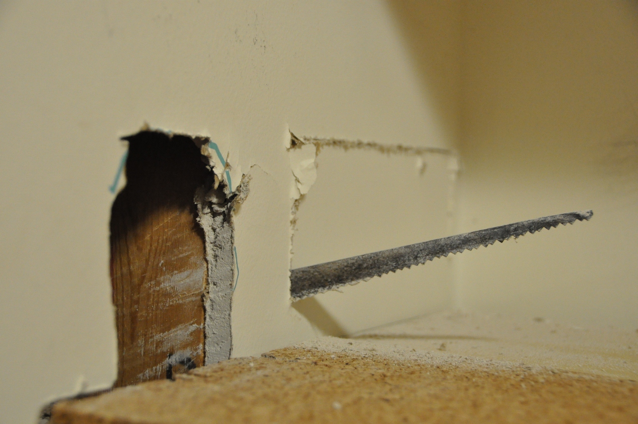
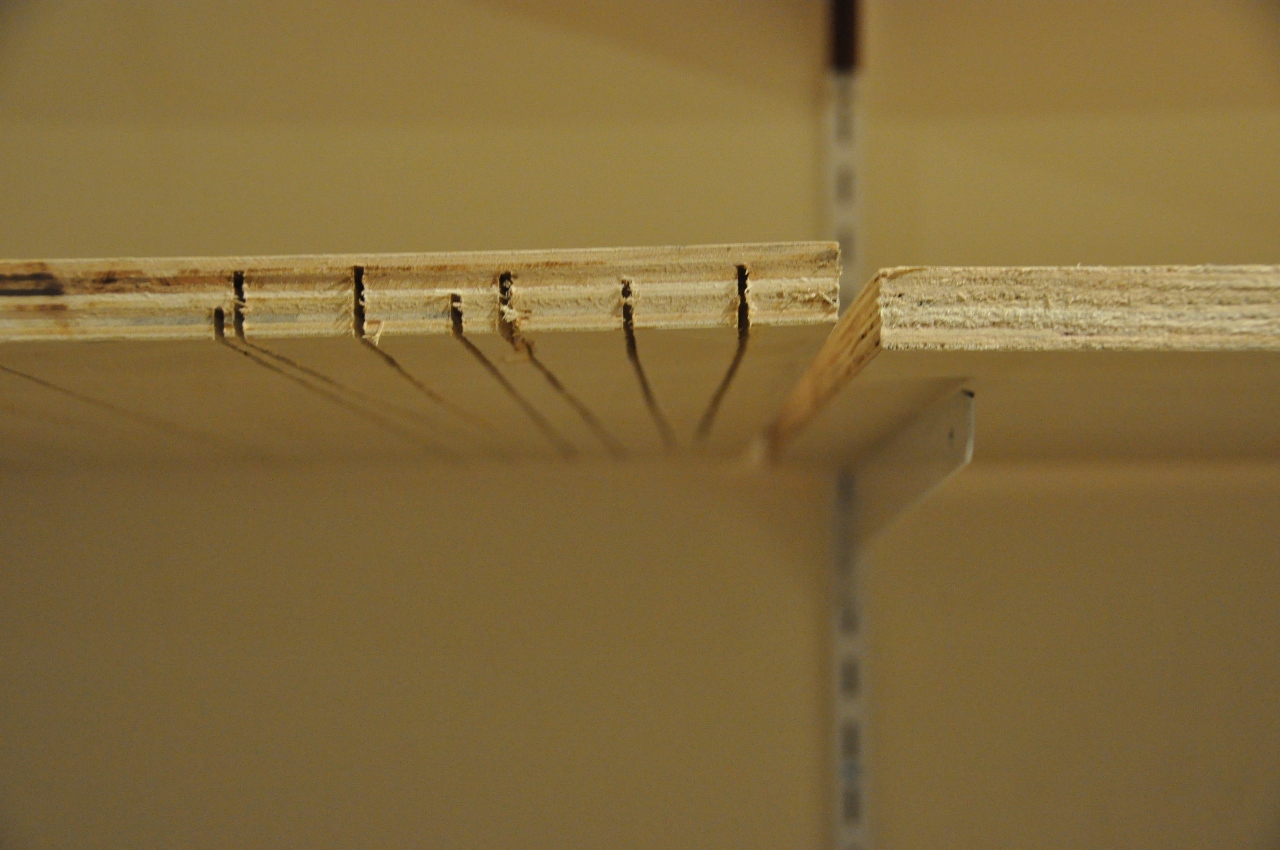
Then the decision to 1] leave as it and hope the joint plate will make it straight, 2] use another piece, 3] cut off the curved portion and put a flat piece in there, or 4] see if cutting some kerfs would allow it to straighten, or at least easier to straighten. Went ahead and put in the kerfs since if they didn't work that section could cut out removing the offending curve.


I then went back to adding a metal channel to stiffen the no-lex piece across the window [had put aluminum angles on the edges when first installing it].

Later the width of a portion of this piece was modified for a section of single track to cross a bridge. The photos below show how I set in place the risers while maintaining level.
The riser is held in place by hand while pilot holes are drilled. The plywood above is then glued and screwed to the riser below.

Then wedges are put in to get the grade where it is needed.

Cross level is then adjusted.

And the riser is then screwed to the bracket.

There are three crossing of the doorway and the original thought was to have a lift-out for the lowest level, a drop down or nod under for the middle and highest level. I have since decided to have hinges for all three. The two lower levels dropping down, the lowest level tucking in about 2 inches closer to the wall. The highest level will rise up. But first was doing a check of the degree of rise as shown in the below photos.

And a check of elevation as marked on the wall

And does it look right?

Notice the curve in the plywood

This photo shows the use of a "standard" shim at one end of the level to check for constant rise along the length of the no-lex.


Various pieces were loosely set in place to look at 1] depth [or width, the distance from the wall to the edge closest to the aisle] considerations 2] the best use of plywood as well as 3] how tight of curve of the track [two dimensional scale drawing tended to be 24" or 27" radii but if we could put in 30" curves would try to see they would "work"].


As stated earlier, how deep should the various levels be? There are two depths on the upper level here and a third depth was looked at.

Some places pieces of track was added to see what one level might look like.

And then compared to how that level fit with the other levels.

One corner viewed at two different times.


The second level of the peninsula was added. First the rounded end was added and a steel channel bolted to the sheet, centrally located on the underside. Here are two underside views.


Topside of the bolt.

Then the frame was made and attached to the wall. The end of the frame away from the wall was held up on 2' X 4's with an additional 3/4" piece to make the required height at the far end. The required height was designed to be short 1/32" to allow for adjustment with wood shims on the legs.

See the upper level laying on the floor in the aisle on the left. It has the rounded end added.

The upper level is in place, the two legs at the end opposite the wall have been added and wood shims added to make the upper level LEVEL. A third leg was added half way between two legs and the wall and a third leg added under the lower level as "belt and suspenders" to prevent any sag that would make either level from being non-level.

Finally, additional plywood was cut to fill in the gaps in the plywood roadbed and set in place [9 photos below].
From outside the train room looking in.

Inside looking out. Three views.


Standing at the doorway and looking to where the photos of inside the doorway were taken.

Two photos of the end of the peninsula. The doorway is to the right and the yard/closet is the doorway on the left.

Notice what appears to be an offset of the two levels. The upper level will be operated from the aisle on the right and the lower level from the aisle on the left - a "mini-mushroom" design.

The photo below is standing in the doorway of the closet/yard area looking back with the peninsula on the left.

Looking back at the closet/yard doorway from the opposite direction of the photo above.

Now to cut plates that will be glued, clamped, screwed together, then get the risers in place.
It's been less than three months since the last post. Yeah! Improvement.
And there has been more "training" - mixture of model operation, photographing and riding the real thing. But the story here is the V&T Rwy progress. All work/progress has been in the main train room. Remember, there is a 2.8% no-lex between the lowest level and the level of the peninsula and a 1.2% grade between the upper peninsula and the next level area before the last 1.2% grade up to the staging in the storage room. Details of the Shay branch are almost final ant that will be the highest level in the main room.

Some additional cross members were added to the lower level framework for the attachment of terminal blocks.
Then elevation markings were put on the wall for the various levels including the no-lex. This led to the discovery of the no-lex in the closet entering the train room almost two inches low. Welllll, that got fixed with the help of Doug. We also double checked my elevation marking in the train room and re-established some of them. Two heads are better than one like measure twice, cut once. We went ahead and installed the piece of no-lex that crossed the window.
Getting back to work a few days later some brackets got hung on the wall and the basic cut plywood sections laid in place.


This was "exploratory" as it was discovered that some pieces identified on the scale sketch actually would better fit elsewhere. One reason for changes was looking at two dimensional sketches with a 3D model is only an approximation of the real world. Depth of areas above the lowest level were adjusted to the real world view and doing some actual checks of a person making a reach.

Another reason for changes is some pieces cut from the "flat" 4' X 8' sheets ended up with bow.

Then the decision to 1] leave as it and hope the joint plate will make it straight, 2] use another piece, 3] cut off the curved portion and put a flat piece in there, or 4] see if cutting some kerfs would allow it to straighten, or at least easier to straighten. Went ahead and put in the kerfs since if they didn't work that section could cut out removing the offending curve.

I then went back to adding a metal channel to stiffen the no-lex piece across the window [had put aluminum angles on the edges when first installing it].

Later the width of a portion of this piece was modified for a section of single track to cross a bridge. The photos below show how I set in place the risers while maintaining level.
The riser is held in place by hand while pilot holes are drilled. The plywood above is then glued and screwed to the riser below.

Then wedges are put in to get the grade where it is needed.

Cross level is then adjusted.


There are three crossing of the doorway and the original thought was to have a lift-out for the lowest level, a drop down or nod under for the middle and highest level. I have since decided to have hinges for all three. The two lower levels dropping down, the lowest level tucking in about 2 inches closer to the wall. The highest level will rise up. But first was doing a check of the degree of rise as shown in the below photos.

And a check of elevation as marked on the wall

And does it look right?

Notice the curve in the plywood

This photo shows the use of a "standard" shim at one end of the level to check for constant rise along the length of the no-lex.


Various pieces were loosely set in place to look at 1] depth [or width, the distance from the wall to the edge closest to the aisle] considerations 2] the best use of plywood as well as 3] how tight of curve of the track [two dimensional scale drawing tended to be 24" or 27" radii but if we could put in 30" curves would try to see they would "work"].


As stated earlier, how deep should the various levels be? There are two depths on the upper level here and a third depth was looked at.

Some places pieces of track was added to see what one level might look like.

And then compared to how that level fit with the other levels.

One corner viewed at two different times.


The second level of the peninsula was added. First the rounded end was added and a steel channel bolted to the sheet, centrally located on the underside. Here are two underside views.


Topside of the bolt.

Then the frame was made and attached to the wall. The end of the frame away from the wall was held up on 2' X 4's with an additional 3/4" piece to make the required height at the far end. The required height was designed to be short 1/32" to allow for adjustment with wood shims on the legs.

See the upper level laying on the floor in the aisle on the left. It has the rounded end added.

The upper level is in place, the two legs at the end opposite the wall have been added and wood shims added to make the upper level LEVEL. A third leg was added half way between two legs and the wall and a third leg added under the lower level as "belt and suspenders" to prevent any sag that would make either level from being non-level.

Finally, additional plywood was cut to fill in the gaps in the plywood roadbed and set in place [9 photos below].
From outside the train room looking in.

Inside looking out. Three views.


Standing at the doorway and looking to where the photos of inside the doorway were taken.

Two photos of the end of the peninsula. The doorway is to the right and the yard/closet is the doorway on the left.

Notice what appears to be an offset of the two levels. The upper level will be operated from the aisle on the right and the lower level from the aisle on the left - a "mini-mushroom" design.

The photo below is standing in the doorway of the closet/yard area looking back with the peninsula on the left.

Looking back at the closet/yard doorway from the opposite direction of the photo above.